
Kenneth Lee III
Friday, May 2, 2025 | 6 minutes
NASA Student Launch Competition
Formal Proposal
The NASA Student Launch competition is an annual event organized and hosted by NASA in which teams of engineers from universities around the United States compete to design, construct, and launch high-powered rockets. Teams submit a project proposal which must be accepted by NASA to be allowed to enter the competition. Each team must then provide comprehensive reports to NASA during the competition outlining their engineering progress to be allowed to remain in the competition, including a Preliminary Design Review, Critical Design Review, Flight Readiness Review, and Post-Launch Assessment Review. All of the details regarding the competition are provided in the handbook as shown below.
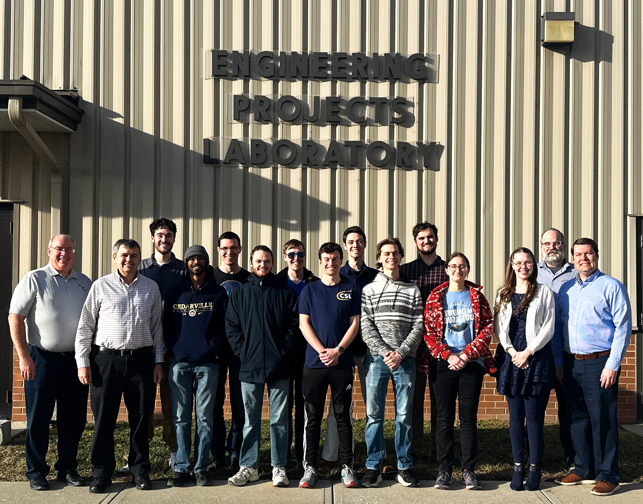
Part of the requirements for achieving the Computer Engineering degree at Cedarville University include completing a senior design project. Successful completion of the project is evaluated by department faculty, who review our reports and presentations at the end of both semesters. My senior design project was working alongside two other electrical and computer engineering seniors to design, build, and test the payload for the Cedarville Student Launch (CSL) competition team. The full CSL team included eight mechanical engineers, one electrical engineer, and two computer engineers, along with faculty advisors.
To start the project, we had several meetings to determine important project parameters such as division of responsibility and reporting procedures. This included both full CSL team meetings and payload team meetings. Another important part of these meetings was decifering NASA’s guidelines for our design and brainstorming how to meet these requirements completely but efficiently. The summary of NASA’s payload requirements is as follows:
Teams are tasked with designing, building, and flying a STEMnaut flight capsule capable of safely retaining four STEMnauts and transmitting, via radio frequency, relevant rocket and STEMnaut landing site data to a NASA-owned receiver located at the launch site.
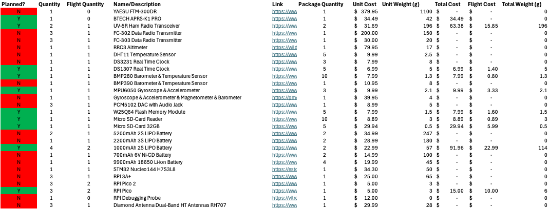
My team and I began by brainstorming and researching what electronic components could be used in the payload, including microcontrollers, sensors, and radio transmitters. For each component we researched, we collected the product’s cost, specifications, power consumption, mass, and a link to access it in the future. This spreadsheet allowed us to have a bill of materials for the payload which could be quickly altered if the team decided to change what components we were using. This spreadsheet also became the basis for other tables including the payload’s mass budget, financial budget, and power consumption allowance to calculate battery life.
Since the project also required the payload to transmit data packets over the two meter band, my team and I needed to get our FCC Amateur Radio Licenses. To do so, I studied for and passed the test to obtain my Amateur Radio Technician License, callsign KF8CDC.
After completing this initial research, we submitted our senior design proposal to our faculty advisor. A copy is provided below.
This same research along with significantly more details regarding operational and safety procedures was submitted to NASA, as shown below. Both proposals were accepted.
Preliminary Design Review
After our proposals were accepted, CSL began to work on what our design for the rocket and payloads would look like. This process requires that for each portion of the overall rocket design, multiple competing designs be proposed then evaluated using applicable analysis tools; this culminates in one design being chosen and formally proposed to NASA in the Preliminary Design Review.
Radio Transmitter Research
One of the core design decisions for the primary payload was the method of radio transmission and reception. NASA’s requirements specified that the payload send data as packets over radio, which is typically accomplished using the APRS protocol.
Our initial design plan was to use the Friendcom FC-302 transmitter on board the payload and the Yaesu FTM-300DR transceiver to receive the payload’s data transmissions, both of which have APRS encoding/decoding functionality built in. Because both of these options were more expensive and had less thorough documentation, our faculty advisors recommended that we begin by using Baofeng UV-5R handheld transceivers for both sending and receiving transmissions.
The cheaper price of the UV-5R handheld radios meant that we could maintain a reasonable budget even in the event of rocket recovery failure during testing, which could destroy the payload. In fact, all of the planning and budgeting regarding rocket payloads was done in such a way that the system could quickly be rebuilt from scratch in the event of testing-induced destruction.
First PCB Implementation
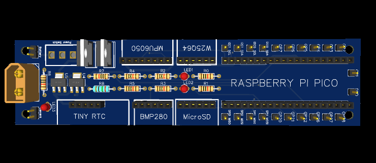
From the beginning, our plan to implement the circuitry needed for the payload was a printed circuit board (PCB), which we would design using the EasyEDA software and purchase from JLCPCB. Our first PCB would use header pins to interface with sensor modules and our chosen microcontroller, the Raspberry Pi Pico. These header pins allow us to quickly remove or replace components for testing or debugging. My first schematic and board layout are shown below.
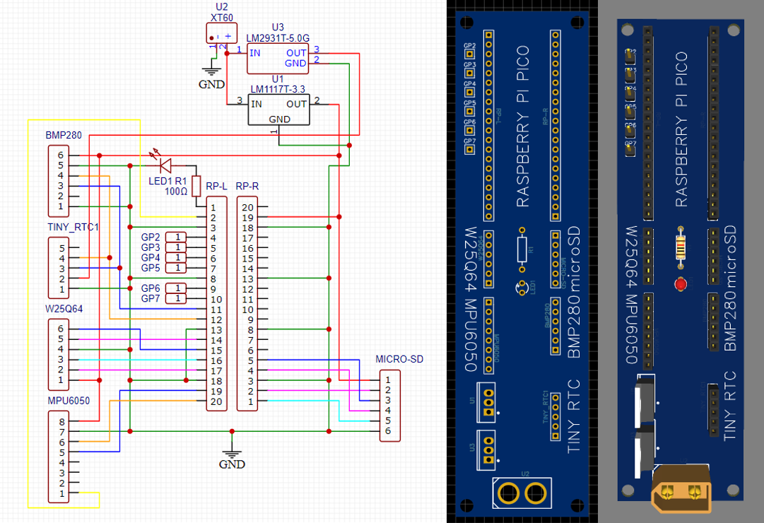
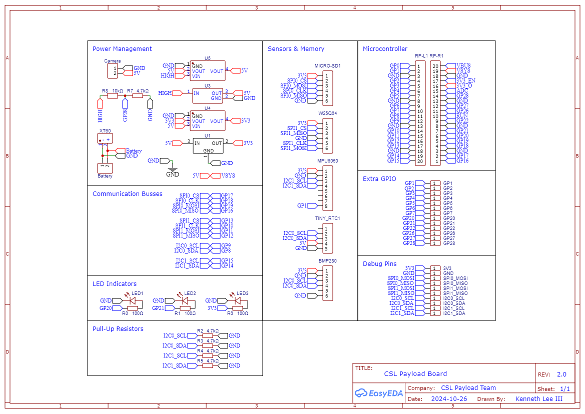
After several meetings with team members and advisors, and numerous design iterations, the PCB was ready to order. Below is the updated schematic we used and a render of the board layout with components added.
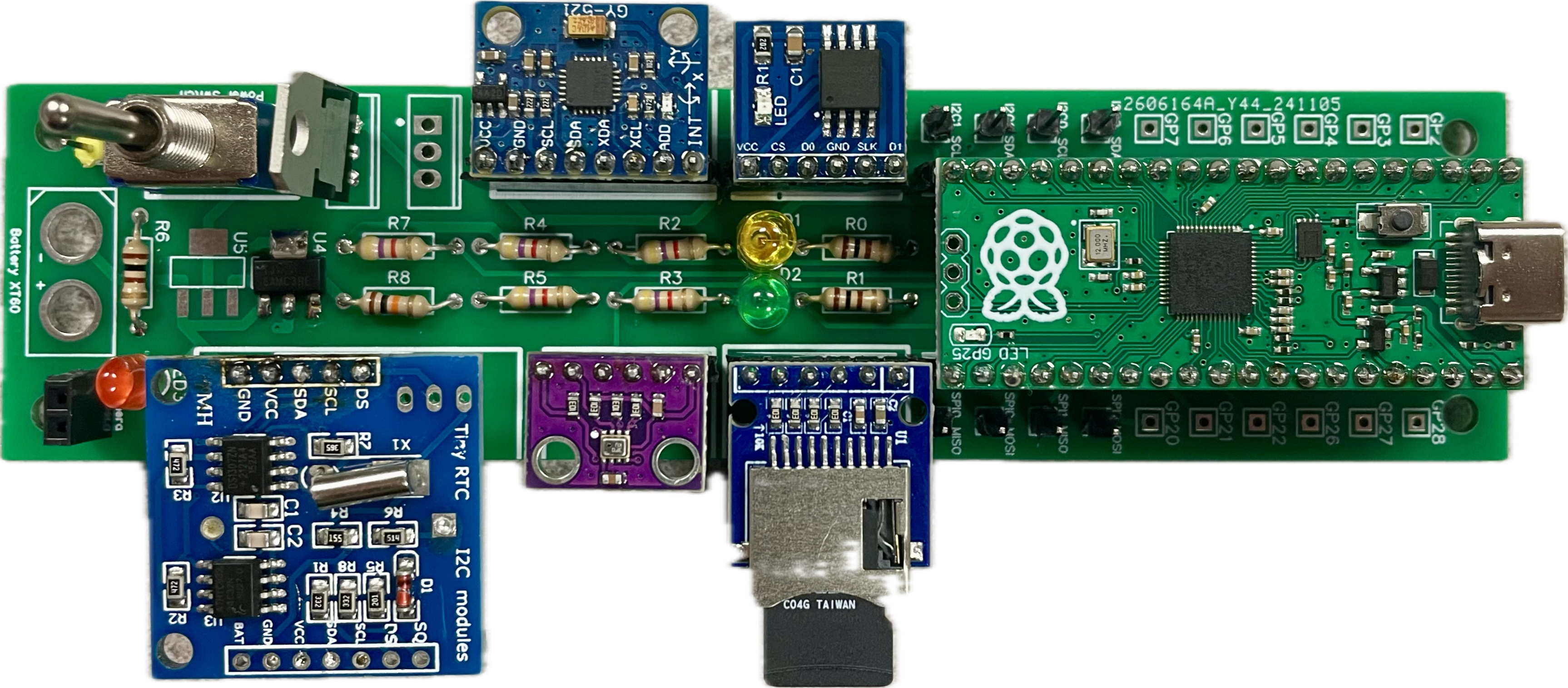
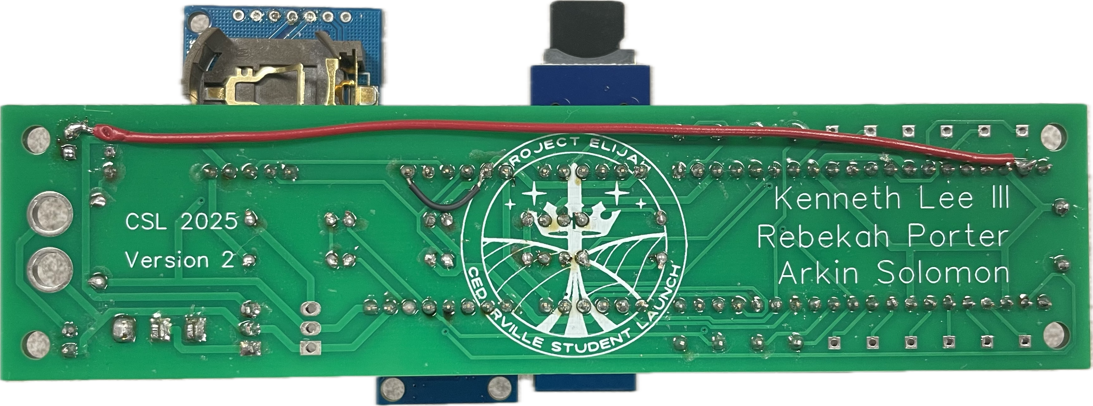
When our manufactured PCBs arrived, we soldered components and headers to the board and tested the Pico and its interface with the sensors. The PCB had a couple small problems which we were able to fix by soldering external wires to make connections. This can be seen in the images of the assembled PCB below.
First CAD Implementation
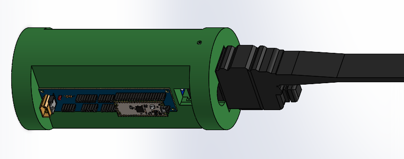
I designed our first CAD iteration in SolidWorks. As a team, we determined that the payload would be located directly below the rocket’s nosecone with the antenna of the radio transmitter pointing up into the nosecone. The main body of the payload would be 3D printed with PLA+ to reduce weight; the transmitter, PCB, and batteries would attach to the 3D printed body. A render of my first CAD implementation is shown below.
Preliminary Design Review Report
CSL submitted our Preliminary Design Review to NASA, which included a presentation, a flysheet, and a 186-page report which is shown below.
Subscale Launch #1
NASA requires each team to have a successful subscale rocket launch, where a three-quarters scale version of the rocket launches and is recovered correctly and safely. The payloads are not required to be included in the subscale launches.
We began the first subscale launch (as well as other launches) with pop tests to ensure that the avionics are performing correctly and that the black powder is sufficient to deploy the parachutes.
TODO: TALK ABOUT THE LAUNCH
TODO: TALK ABOUT LAUNCH RESULTS