
Kenneth Lee III
Wednesday, December 3, 2025 | 3 minutes
Bench Power Supply
Brainstorm
The idea to design and build a bench power supply came from numerous small projects in which I needed to supply power to a circuit, sometimes requiring a fixed voltage, and other times requiring an adjustable voltage or current. I began by brainstorming my ideas with ChatGPT, telling it my project goals, constraints, stretch goals, and current available supplies. As shown in my conversation with ChatGPT here, I conversed with it about what protection circuitry would be advisable as well as what items I would need to buy for the project.
Design
Circuit Design
Next, I sketched a wiring diagram to indicate how I wanted the internal circuitry to be connected, as shown in the diagram below.
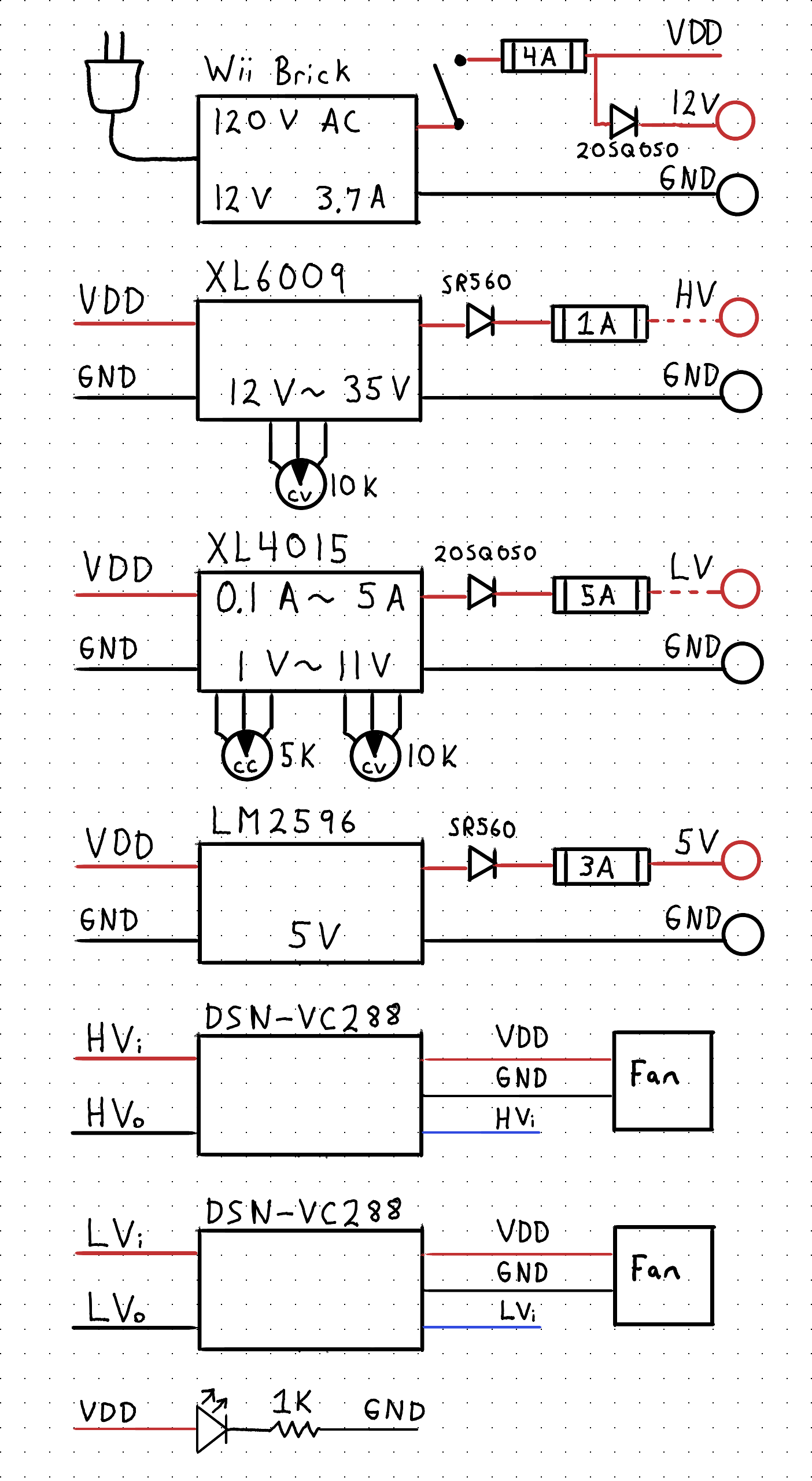
After confirming that ChatGPT was unable to find any errors with my schematic, I used it to purchase the parts I needed from Amazon and ElectroPeak.
Interface Design
After the circuit design was complete, I began to tinker with the power supply’s interface. This meant choosing that the four output rails (fixed 5V, fixed 12V, adjustable <12V, adjustable >12V) would be banana sockets. The two adjustable voltage outputs also included a voltmeter and ammeter gauge with potentiometers to control voltage and/or current levels. This is shown in the diagram below.
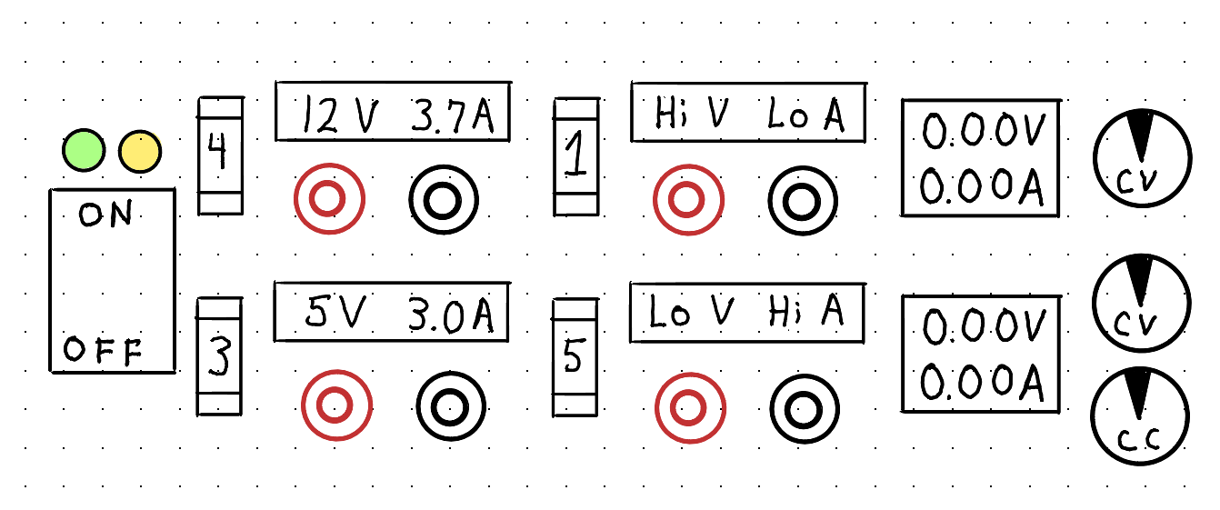
This interface became one of the core design constraints for the CAD design of the power supply.
CAD
Instead of starting from nothing for the physical design of the power supply, I decided that the top and bottom would use two steel plates left over from other objects that I have disassembled. The height of the power supply would be determined by how much room was needed to fit the interface I designed as well as all of the internal wiring. Using these constraints, I designed the complete power supply in Onshape, which can be accessed here.
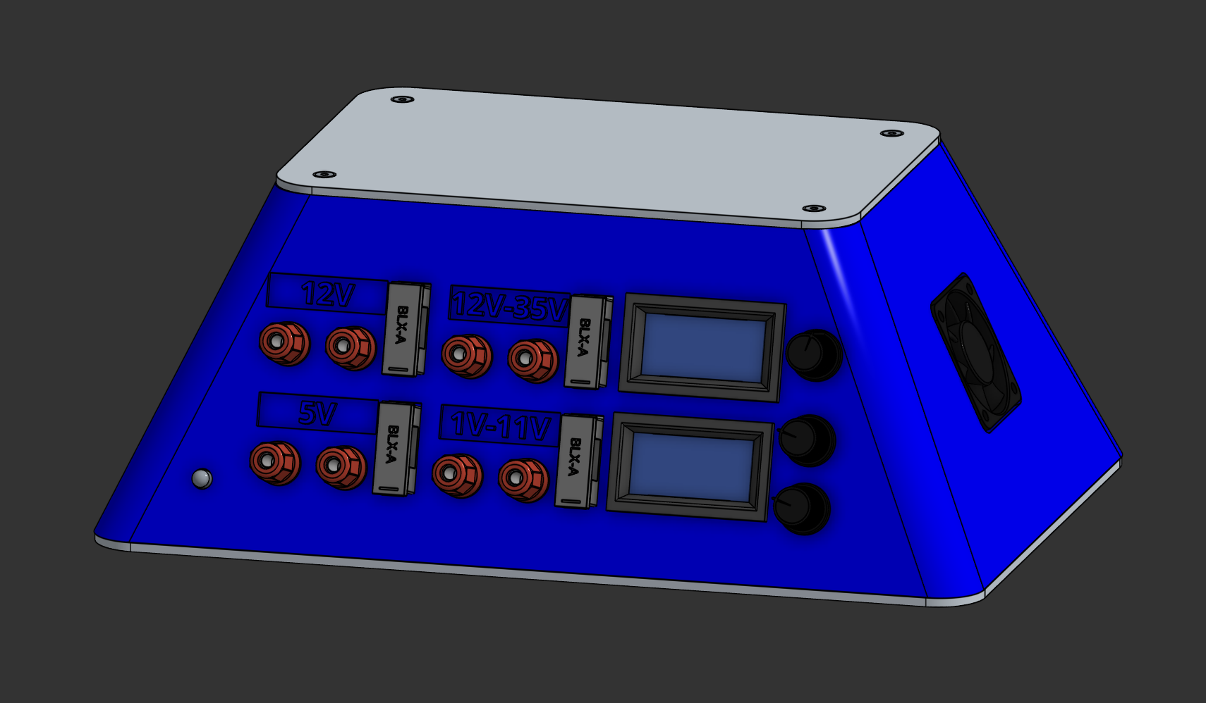
The design is such that the outer shell can be 3D printed and heat set insert nuts can be affixed to allow the top and bottom plates to bolt on. All other interface components either screw on or snap into place.
Assembly
My first attempt at 3D printing the power supply was with ABS filament. ABS has a tendency to contract as it cools, which causes the print to warp during printing. This is especially pronounced for relatively large, thin objects such as the shell of the power supply. When the first several attempts all failed due to extreme warping, I switched to PLA, my go-to filament.
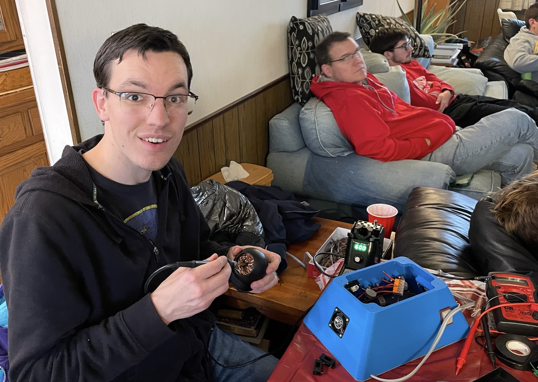
I performed all of the assembly and wiring during the Thanksgiving holiday with the assistance of my younger cousin. A significant amount of soldering was necessary using a variety of techniques, along with many WAGO connectors. In total, nearly seventy wiring connections needed to be made within the confines of the box.
Results
The resulting power supply has four output voltage rails corresponding to the voltages I use most often. The fixed 5V and 12V rails are convenient for many devices that need those voltages. The low voltage output, which uses a buck converter, has two potentiometers which control the voltage level and maximum current draw respectively. The high voltage output, which uses a boost converter, has one potentiometer to adjust the voltage up to 35V. Each output is individually protected with a fast-blow fuse and Schottky diode.

This was the first time I chose a specific project to accomplish during the Thanksgiving holiday break, and I really enjoyed doing it with the help of my cousin. My uncle and I were able to talk over the holidays about how it’s been a tradition in my family’s past for the engineers to come together around a fun project and take some ground on it during the holidays. I hope to continue this tradition in the future!